Replicates a programmed waveform of any shape or polarity
- Creates a constant current replica of analog waveforms
- Amplitude of the output current is voltage controlled
- Input voltage from –10V to +10V
- 3 current ranges from 100 μA to 10 mA
- Built-in test resistors
- Digital display shows current being delivered for non-varying currents of adequate duration
- Output offset adjustment ±70 V compliance range
- Choose batteries: NiMH with Charger (A395RC), Alkaline (SYS-A395D), NiMH (SYS-A395R)
Options
| Part # | Description | Battery Type | Includes Charger |
| A395RC | A395R with an A362 Battery Charger | 17 NiMH 9V Rechargeable Batteries | Yes |
| SYS-A395R | Linear Stimulus Isolator | 17 NiMH 9V Rechargeable Batteries | No |
| SYS-A395D | Linear Stimulus Isolator | 17 Alkaline 9V Batteries | _ |
Benefits
- Amplitude of current is voltage controlled
- Built-in test resistances
- Error LEDs illuminate when current is less than commanded by control voltage
Applications
- Neuroscience
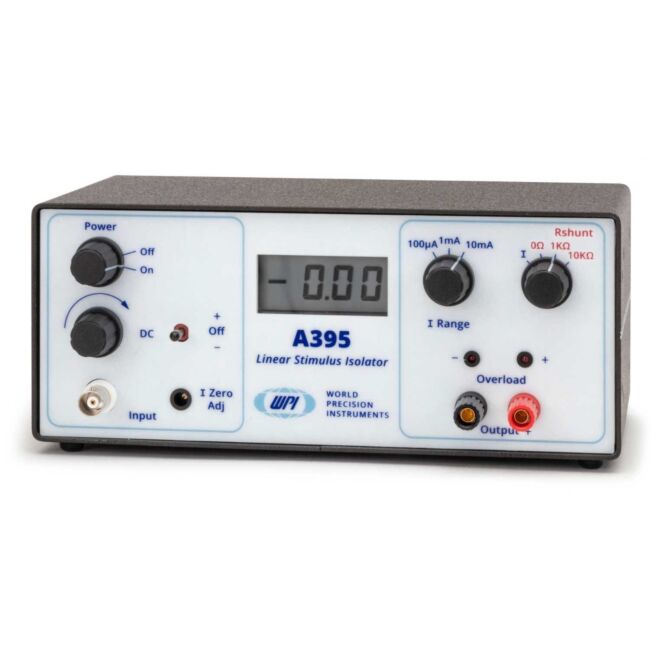
All WPI stimulus isolators are designed to supply constant current, because current threshold (not voltage) is the most quantitatively reproducible parameter for stimulation of nerve and muscle. Model A395 dispenses current reproducibly from its Output terminals; the amplitude being determined by the selected current RANGE and the input voltage. Current amplitude is “constant”, that is, load resistance independent, provided that the I x R (load) product does not exceed the available battery supply voltage. A visual indicator (the compliance LEDs) displays if I x R reaches this limit. When the unit is out of compliance, one of the two LEDs (labeled – and +) illuminate, depending in which direction the current is flowing. Model A395D can generate a voltage of 70Vor more across its OUTPUT terminals. You can be sure that the amplitude of the current is as dialed as long as the voltage drop across the load (stimulus electrode path) does not reach the magnitude of the supply voltage. The compliance LEDs will then be visible. Then, you would know that:
• Too much current was dialed for a given load or
• Inter-electrode resistance was too high or the electrode circuit path was open.
User defined output current of various forms
Model A395 generates a user-defined output current of wave shape; DC, AC, pulse and combinations. Battery operated, photoelectrically-isolated from the input voltage drive, the instrument regenerates output currents which are linearly proportional to the analog voltage waveforms provided by your D/A converter or signal generator (see diagram below).
The A395 is ideally suited for data acquisition and stimulator generators.
Current delivery for selected ranges
A 10 V input produces the maximum output current for the current range selected. (For example, 100 µA, 1 mA, or 10 mA) Front panel controls allow DC current to be generated. Externally applied signals can be superimposed simultaneously (DC offset). Warning lamps indicate open circuit or excessive current conditions.
Digital meter shows DC or average output
The digital display meter shows the measures DC current or the average output current. Overload lamps indicate when output voltage has reached positive or negative compliance voltage limit.

NOTE: Not intended for human use.

